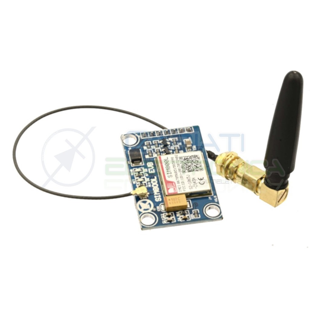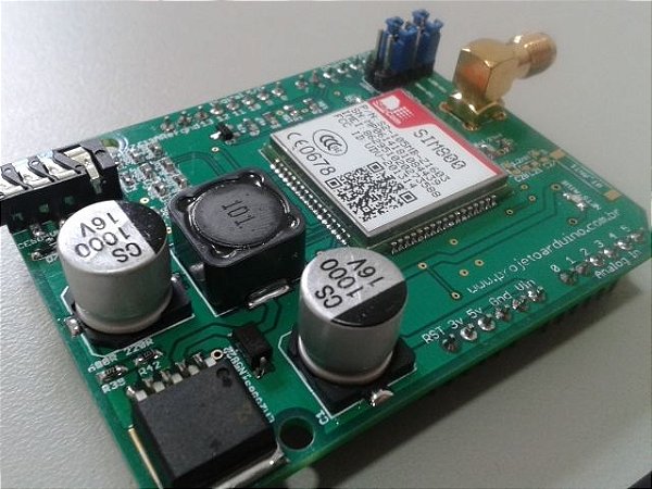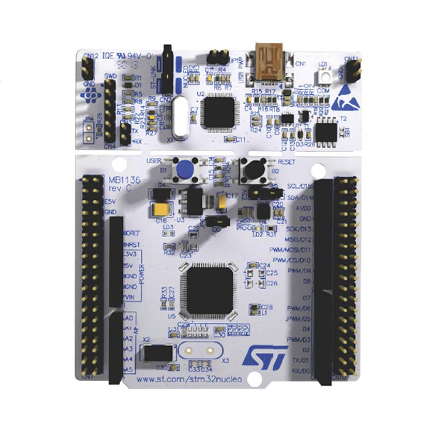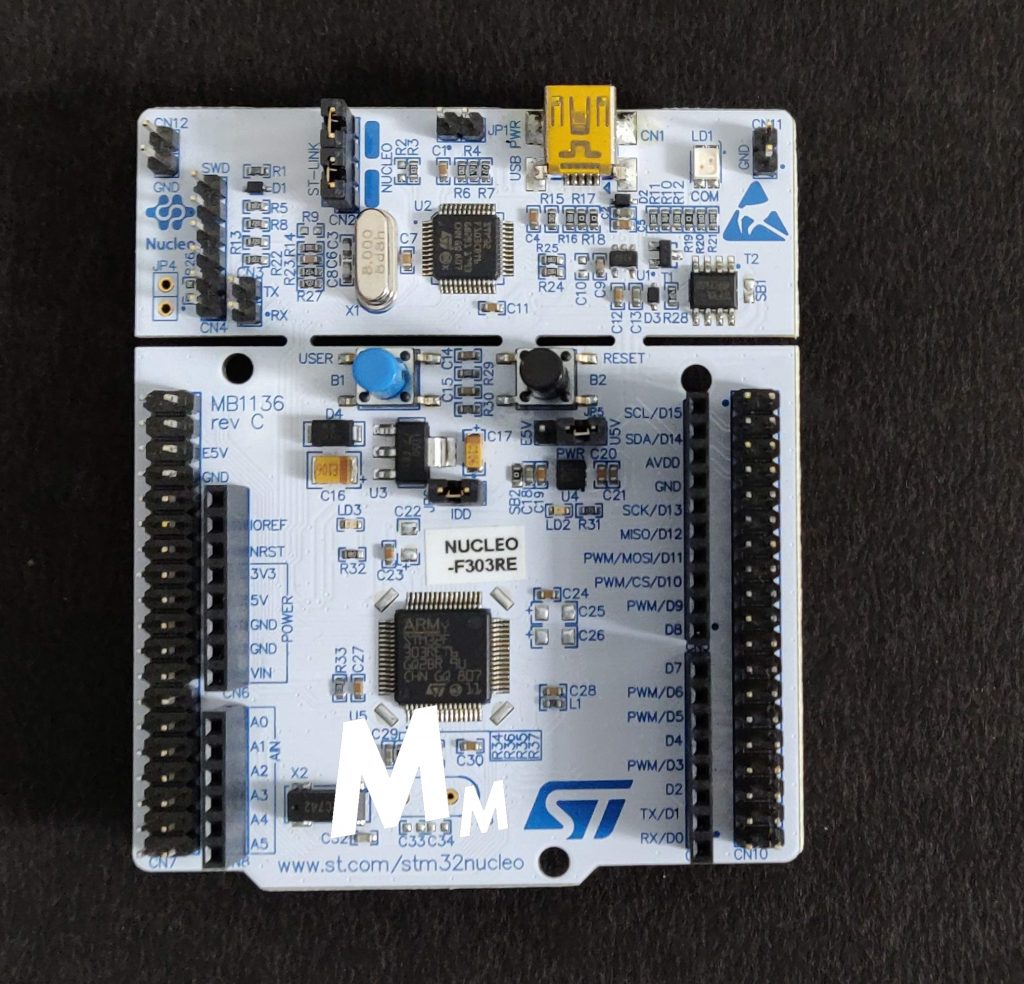

Especially the Alternate Function assignment. I was using STM32F0 Discovery board, so the pins and functions are different.
#Sim900 st nucleo code
Here i am using CooCox with inbuilt libraries for fast code implementation NVIC_EnableIRQ(USART1_IRQn) //NVIC enables the IRQ USART_ITConfig(USART1, USART_IT_RXNE, ENABLE) // ONLY RX mode config
#Sim900 st nucleo serial
Serial Communication, SIM900, ST Nucleo F401RE. UART1_BT.USART_HardwareFlowControl = USART_HardwareFlowControl_None Questions Tagged with SIM900 Unanswered Questions for tag SIM900. UART1_BT.USART_StopBits = USART_StopBits_1 Short NRESET (pin 16) to GND for a moment.
#Sim900 st nucleo rar
UART1_BT.USART_WordLength = USART_WordLength_8b Setup flashing tool connect it to SIM900A, set default speed of 460800 baud, choose firmware to flash from unpacked RAR file, select don’t check file name check-box and press start download button to see Power On/Reset Target message. GPIO_PinAFConfig(GPIOB, GPIO_PinSource7, GPIO_AF_0) GPIO_RX_Pin.GPIO_PuPd = GPIO_PuPd_NOPULL GPIO_RX_Pin.GPIO_Speed = GPIO_Speed_Level_1 * Configure USART1 pins: Rx * - PB7 Alternative as TIM1 uses 4 channel PWM generation */ RCC_AHBPeriphClockCmd(RCC_AHBPeriph_GPIOB, ENABLE) RCC_APB2PeriphClockCmd(RCC_APB2Periph_USART1, ENABLE) Make sure your grounds are common, or else it won't work. This is the code which i used for USART Receive only mode at 9600 Baud Rate. If((Timeout = 0)||((HAL_GetTick() - tickstart ) > Timeout)) While(_HAL_UART_GET_FLAG(huart, Flag) = RESET) To be exact, it goes inside this first if and waits for the next character to be received: /* Wait until flag is set */ When I step into the HAL_UART_Receive function in debug mode, I see the program stuck inside static HAL_StatusTypeDef UART_WaitOnFlagUntilTimeout() function. If( HAL_UART_Receive(&huart1, (uint8_t*) aRxSIM900Buffer, RXBUFFERSIZE, 10) != HAL_OK) HAL_UART_Transmit(&huart1, (uint8_t*) Message, TXATMESSAGESIZE, 1) #define COUNTOF(_BUFFER_) (sizeof(_BUFFER_) / sizeof(*(_BUFFER_))) My main function looks like this: #define TXATMESSAGESIZE (COUNTOF(Message) - 1) I think there's a configuration mismatch between Nucleo and the modem but couldn't figure it out yet.

I use the oscilloscope to see if the binary bits are transmitted to the modem and it works fine.

I've tried sending "AT\n" "AT\n\r" too but neither was giving the proper result. Now I'm trying to send "AT\r" command and receive the "OK" or "ERROR" from the modem but it seems that I get nothing from it. GPIO_InitStruct.Alternate = GPIO_AF7_USART1 = UART_HWCONTROL_NONE Īlso the GPIO initialization is as follows: GPIO_InitStruct.Pin = GPIO_PIN_9 | GPIO_PIN_10 The SIM900 can communicate with an external.
#Sim900 st nucleo how to
I am used to developing on Arduino and Espressif boards so I was expecting something like a serial monitor to debug the board but apparently things are not so simple on STM.I'm trying to connect Simcom SIM900 to Nucleo-F411RE using the following configuration for USART1: void MX_USART1_UART_Init(void) In this tutorial, well learn how to send a text message using an STM32 microcontroller and SIM900 GSM module. I have the right code in place, but unable to receive the output over USB. I have initialized the components in the right order (DMA before the ADC). I have been at this for weeks and cannot figure out why I cannot receive any data. The only issue is not being able to get that data onto my computer. I am also able to detect and measure the output of the sensor using the Logic Analyzer. On a hardware level (as I mentioned earlier) I know that the signals are being generated.

I tried varying the Baud Rates as well but no luck, not even garbage values. I confirmed that I am using the right port. When I tried doing the same thing, using the same serial port reader, I don't see anything showing up in the console. When the person in the video opens a serial port reader (CoolTerm), he begins to see data showing up in the console without configuring anything (just pushes start). Then the output of the ADC is programmed to be sent over USB to the host computer. One of the interdependent signals triggers the internal ADC to read the sensor output via DMA (4th internal signal). Basically there is a master clock signal, and two other signals which are interdependent. In fact, I have replicated each and every setting to match what the video shows. This video tutorial that I have been following has the same configuration. Middleware -> USB_DEVICE -> Communication Device Class (Virtual Port Com).Connectivity -> USB_OTG_FS -> Device_Only.RCC -> HSE -> Crystal/Ceramic Resonator.I have the following configuration regarding connectivity: I confirmed (using a logic analyzer) that the code is generating the correct signals. I have programmed the board via CubeIDE and the program flashes onto the board without any problems. I generate 3 clock signals to drive the sensor. I have been trying to interface a sensor using an STM32F401RE Nucleo board but failing to receive sensor data from the board.


 0 kommentar(er)
